6U desktop network rack build
My “core” LAN network consists of two rackmounted switches and a router. After moving into a new apartment, I didn’t want to keep them in a zero-ventilation closet on the other side of the apartment, so I thought I’d put my massive desk to good use and build a small rack to stick the network gear in, and keep it on my desk for ease of use and good ventilation.
The components
The pre-existing network components are:
- Mikrotik CRS112-8P-4S-IN, primarily used for its 802.3af/at Power-over-Ethernet output capabilities. It is used to power a wireless access point, the router and three Raspberry Pi’s.
- Mikrotik hEX S, the router. It’s powered purely with 802.3af/at PoE from the switch to avoid using a socket unnecessarily.
- TP-Link T1700G-28TQ, just for the ports. Every port in the CRS112 are used up, so this thing lets me have free ports for when I need ‘em. It also has four SFP+-cages - I’m not currently using them, but I’m considering connecting my desktop and lab to the switch with fiber for a 10 gigabit connection to my network storage.
The new stuff to complete the build are:
- A DIGITUS keystone patch panel. Whatever cables I pull to the rack will go into this patch panel, and from there into either switch with some quarter-meter patch cables. Edit 31/05/21: the keystones I got are crap.
- A Varytec power distributor to plug things into. I chose this one since it has plenty of ports - eight - and a power switch on the front. Many others I found had the switch on the other side to the ports, which wouldn’t fit me.
- A 1U Thon rack shelf to mount the power supply for the CRS112, and possibly some other things in the future.
- And finally, a Millenium Steel Box 6 6U rack to house everything in. It’s 300mm deep, which is enough to fit everything I want and shallow enough to fit neatly on my desk. It also has square holes for cage nuts, which is ideal.
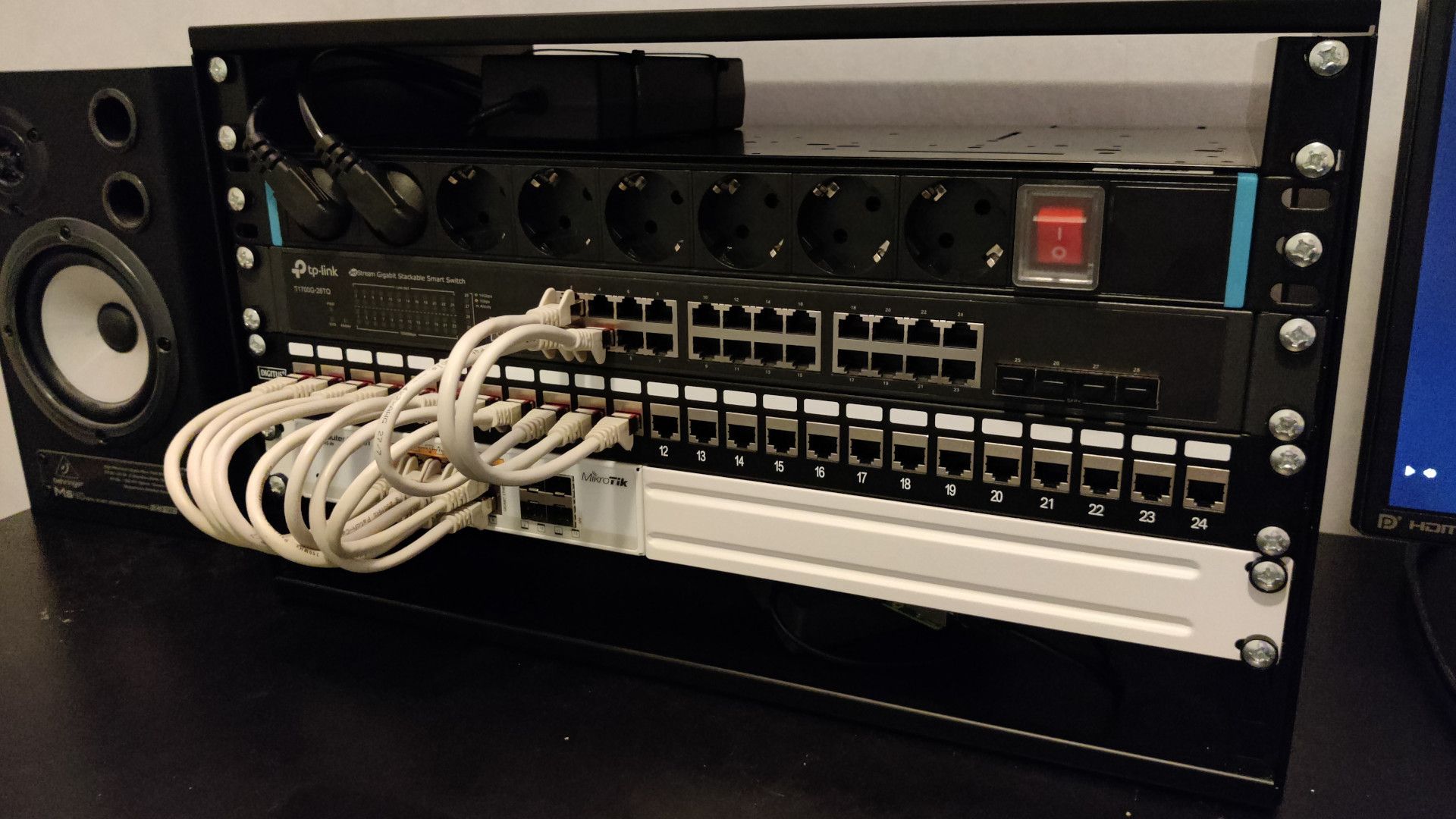
The build
I had some pre-existing cage nuts and screws to mount everything in the rack with. I ended up laying out the devices in order from top to bottom;
- shelf
- power distributor
- T1700G
- patch panel
- CRS112
- empty
I might experiment with moving the power distributor to the second-to-bottom slot, routing the power cables underneath it and moving everything up one slot, so whatever ‘auxiliary’ devices I plug into the power distributor wouldn’t droop in front of the switches.
The router and Raspberry Pi’s are plugged directly into the back side of the patch panel. I use some Chinese PoE-splitters to power the Pis. Two of them are 3B+’s, one is a 3B. The PoE-splitters allow for only 100Mbit links instead of gigabit, but the Pis wouldn’t use gigabit anyways. The 3B uses a 100Mbit link anyways, and while the plus-models negotiate a gigabit link, they still run Ethernet over the USB2 bus so it’s limited to around 300Mbit in practice. Dropping that down to 100Mbit doesn’t really matter for my use.
The router, however, does do both gigabit links and active PoE, just like the 802.3af/at standard allows. It’s plugged into two ports on the switch, the other one being a VLAN trunk port and the other a VLAN access port. Via the trunk, it gets access to WAN and to a transit network into a separate lab network (outside the scope of this post, sorry). The access port is just for the local LAN. It behaves kind-of like a router-on-a-stick setup.
The PoE devices are just laying around behind the switches, which isn’t very ideal nor clean. I’m planning of getting some cases for the Pis I could mount to the shelf on the top to protect them from accidental short circuits, and to hold them in place. Right now they’re just floating on top of the cables to isolate them from each other and the metal rack case. Fun fact; you can kill a Pi 3 by shorting its 5V rail to its 3.3V rail while its powered. This is easily done accidentally, since the GPIO header has both a 5V pin and 3.3V pin right next to each other on the top side. I originally had four 3B+’s, but two of them have died, likely due to this issue. I don’t want the last two to die by shorting them to the metal rack case or something such.
The link between the CRS112 and the T1700G-28TQ is via the patch panel to avoid “jumping” a cable over the patch panel, which makes for cleaner cabling.
The CRS112 comes with optional rackmount brackets I had to dig out from underneath a pile of boxes, but I found ‘em and screwed ‘em on. The device has two power DC power ports, one for 18-28V and one for 48-57V. If you plug power into the higher voltage one, it’ll allow the device to output 802.3at (sometimes called “PoE+”). The Raspberry Pi PoE-splitters require 802.3at, so I’m using a 48V 3A power supply. I’ve zip-tied it to the shelf on the topmost position. I measured its output and it’s actually half a volt shy of 48V, but the PSE in the CRS112 doesn’t seem to mind. It’s outputting a nice 49V on each PoE port.
The keystones fit into the patch panel just fine, but they’re a bit fragile and some fit the cable on either end very tightly. I’ve already had a mounting tab break off one keystone, so it’s sort-of loosely held in place by the cables on both ends. They likely won’t tolerate being attached and detached often, but then again they’re not supposed to be moved around that much.
I grabbed some small rubber feet from the hardware store to stick to the bottom of the rack to stop it sliding around so easily.
The future
Temperatures in the rack seem fine, albeit a bit high. The 48V (well, 47.5V) power supply for the CRS112 gets quite warm, but not so hot I couldn’t hold my hand on it. Both the CRS112 and the T1700G are passively cooled, so I’m assuming they’re fine not having any active cooling. To the touch they’re a bit too warm for comfort in my opinion, though. I have a couple of 40mm Noctua fans laying around, so I might try and mount a fan into one or both devices, assuming I can get 12V power from somewhere. I’ve been inside the CRS112 once already, and it does have three solder pads labeled “FAN”. Unfortunately they don’t seem to be active, so I’ll have to figure out some other way to get 12V out. I don’t know what’s the deal inside the T1700G, but I’ll figure something out if need be.
The patch panel still has another 12 ports free, and the T1700G has almost all its ports free, so there’s plenty space for future port needs. I’m thinking of getting a small 1U server to mount in the last free space in the rack that could host some local storage. It’d have to be pretty shallow for a server though, since the rack has only 300mm of clearance.